Lithium batteries have overtaken all other batteries as the technology to use for most electronics projects. Lithium wins with energy density (size), longer life and good power outputs. There are also other positives for the technology.
However Lithium cells are not always as easy to use as the older Ni-Cd, Ni-NM cells and SLA (Seal Lead Acid) batteries. The reason is Lithium cells need to be voltage balanced when charging. Failure to do so reduces the life as one or more cells can become unbalanced and overcharged. Over charging can also lead to fires in extreme cases. Lithium cells can also be damaged if discharged too low. Recharging lithium batteries that have dropped below 2.5V can also be dangerous if precautions are not taken.
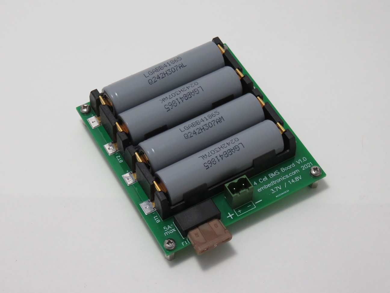
This board is ideal for prototyping in projects. It has a Battery Management System (BMS) that protects the cells from over charging and over discharging. It also balances the cells. Just install 4 18650 cells and you are ready to go. No having to spot weld cells into packs!
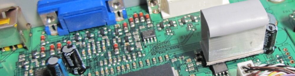
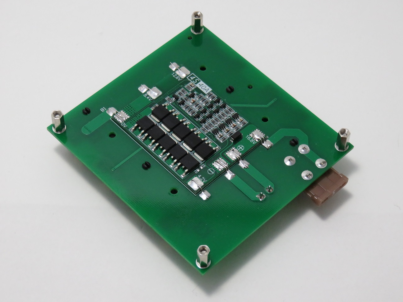
The board contains a 40A BMS, however as it’s designed to use with ‘standard’ non high discharge cells so 5 amps is the maximum recommended discharge rate.
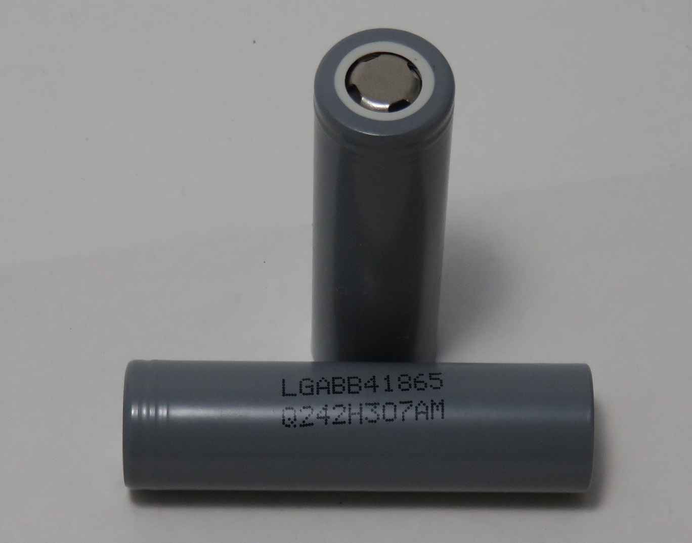
I use and stock the LG Chem LGABB41865 Cells. These are standard discharge rate 2.6Ahr cells, with a max discharge rate is 5A (5 to 45Deg C ambient temperature). See datasheet for normal charging and discharging rates. These are perfect for general projects, however can not be used in high discharge motor applications like power tools. For this high-discharge Lithium Ion cells are required.
I stock LG Chem LGABB41865 Cells in Adelaide for locals, however I will not ship these interstate.
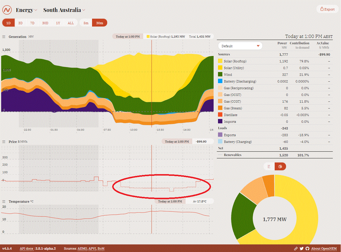
Solar home owners in south Australia and also Australia are facing a problem where the energy they generate from solar that can’t be used during the day (and therefore exported to the grid) will be worthless soon. The problem we have are wholesale power prices during the day are so low and in some cases negative due to this oversupply in solar energy. Feed in Tariffs (FIT) have been dropping for the last few years from high prices of 50-60c to a low of 5c (AGL). Within a few years I expect export will be worthless.
The snapshot from last week, shows the electricity prices in South Australia was negative for most of the sunlight “solar generating” hours. This was a Saturday with mild weather which reduces demand therefore large negative periods.
If you have money to burn, you can install a Tesla Powerwall 2 or similar to storage energy generated during the day to use during the night. This technology is proven and all works, just the economics is not good. In my case and the case for many home owners the system would take 15+ years to payback.
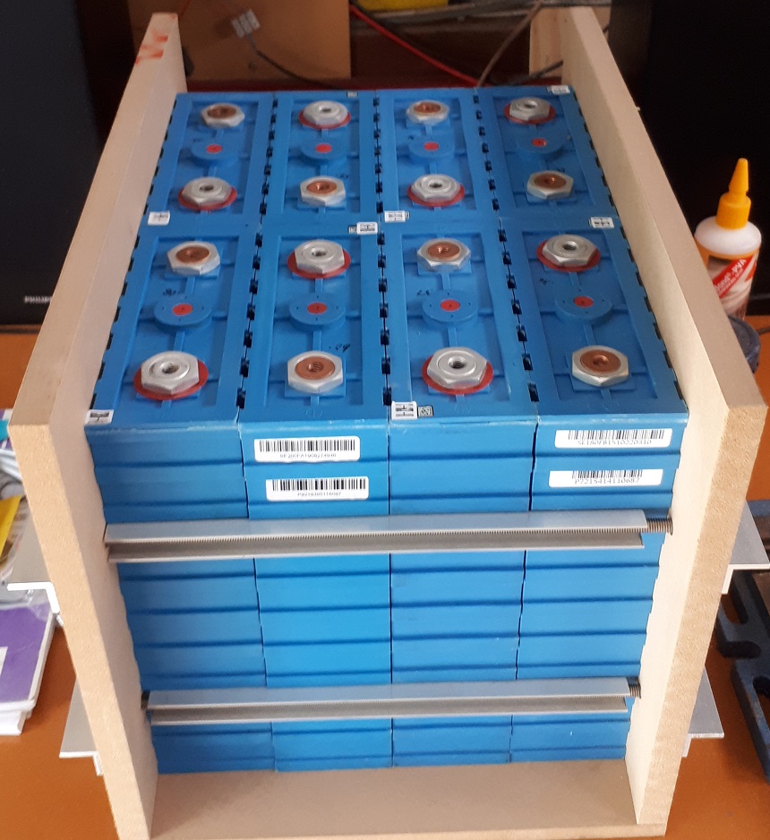
I upgraded a small off-grid system months ago to new LiFePO4 cells. In the process of buying new batteries, I decided to double the order. This gives me a 2nd battery bank of 8x 200Ahr LiFePO4 cells or about 5kWh of storage capacity (4.2KWh useable) to play with.
5kWh of LiFePO4 cells
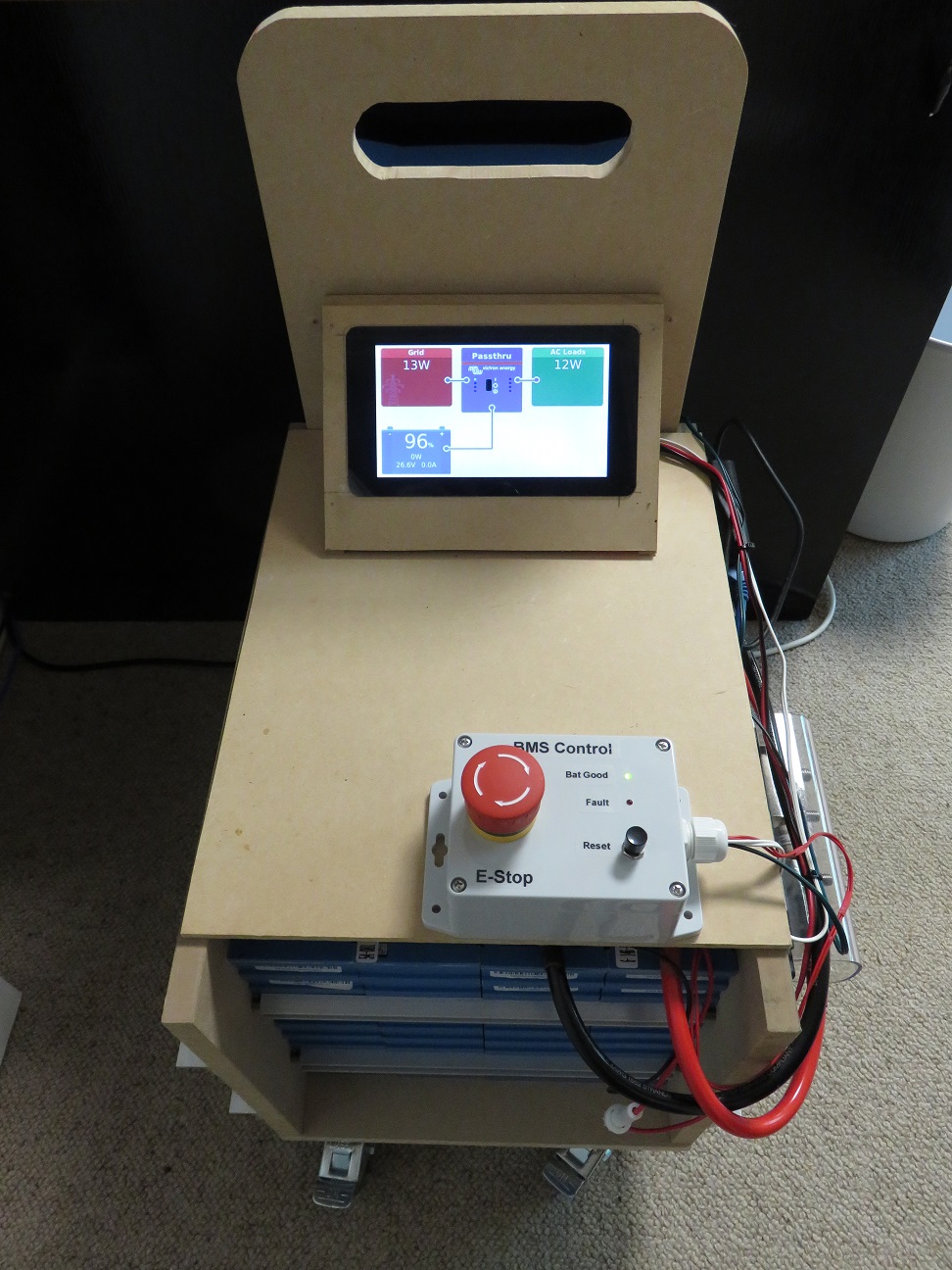
Introducing my new UPS/ESS below. I wanted to design a simple plug in semi-portable system. Something that could be used by anyone owning their home or renting. I wanted to be able to charge up the battery using my own solar energy and then run loads at night or on cloudy days from the battery. The hardware is very simple, a Lithium battery bank (24V/200Ahr) with custom BMS wired into a Victron Multiplus Inverter. The Multiplus inverters are brilliant as they come with a inverter, battery charger, automatic transfer switch and more importantly, software controllable.
The first prototype on wheels
Out of the box, these Multiplus unit can be programmed as a UPS, but in my application the smarts are in the custom software on a controller. Just like a UPS it plugs into a powerpoint (GPO) for charging and then my loads (Computers and my whole electronics room) runs from the output. The unit is setup so it can’t export energy into the powerpoint which is a legal requirement, so really is just a programmable UPS.
This controller connects to my home automation system via Wi-Fi to read the data of how much power I’m importing or exporting. When the sun comes up and there is enough spare power generated from the solar to cover the connected loads, the battery charger kicks in and starts slowly charging the battery. As more power is generated by the solar, the charging rate (Amps) increases to use up any exported power just like a fixed home battery would.
Touch screen controller running Victron’s software – charging at the full 25A set
Then at night, it switches to inverter mode and runs all my loads from the stored solar power I had generated that day. Also if there are cloud cover or a large load turned on in the house, the system can switch the connected load to battery to reduce the power imported. As always there are lots of extra smarts and protection to keep the batteries within a safe State of Charge (SOC) in case of a power blackout. This can be customised in software, just like a Tesla Powerwall.
This is just part of my demand management for my home. I’m also controlling non-critical loads like dehumidifiers and some lighting. The next goal is to control the air conditioning for the home.
So what does it all cost? Is it worth it? This will be covered in a following post!
I have been using the Open Energy Monitor’s content management system (emoncms) for at least the last 10 years to log and monitor various sensors around my house. The software is brilliant in my view, however Home assistant is slow taking over with all the new energy monitoring dashboards, etc. I think if I was to start again, I would run everything from Home Assistant. Currently I run home assistant mainly for control.
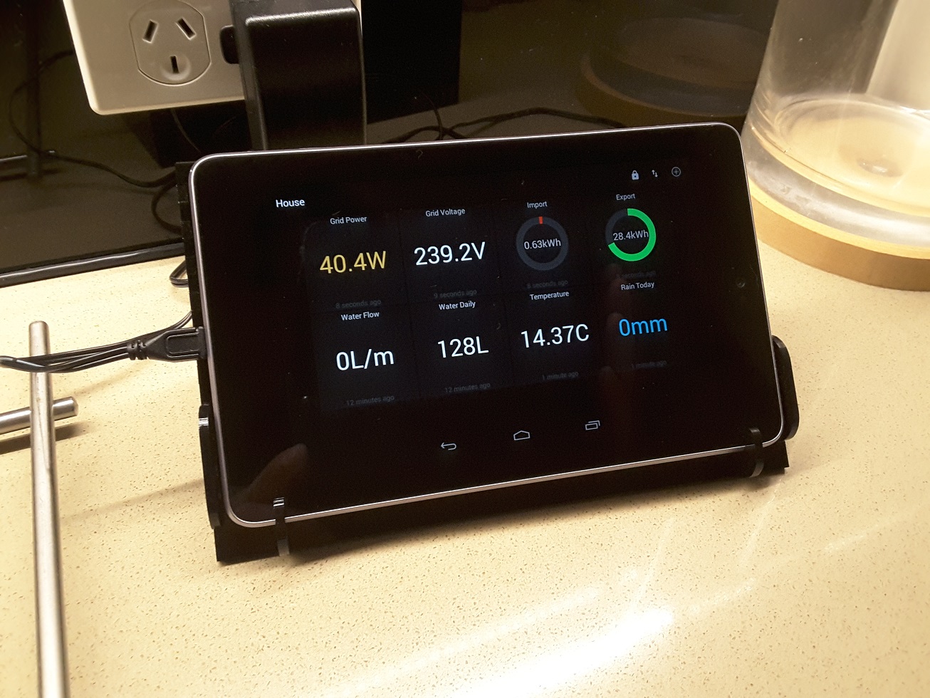
As a hardware person, I would always design and build my own sensors that would talk W-Fi directly to my local emoncms running on a beaglebone (Now a raspberry pi). I now have hundreds of data points coming in from all different types of resource monitoring and environmental sensors. Water, Electricity, Temperature, Humidity, Tank Levels, CO2, PM2.5, PM10 and much more as it’s always expanding. All the data can be displayed on the normal emoncms dashboards, however I wanted a basic real-time display in the kitchen that I could just look at.
As I can pull the data from emoncms via MQTT, you can download apps to make dashboards. That is all I have done here using MQTT Dash. The main screen displays Grid Power, Grid Voltage, Grid Import for today, Grid export for today, Mains Water Flow, Water usage for today, outside temperature and rain fall since 9am.
This is a great way for me to understand my electricity and water usage in real time. As a household with solar panels, I can save money by using my own energy directly from my solar panels during the day. The goal is bring the imported energy (Energy from the grid into your home) down to the lowest possible. I have now achieved very low imports with some smarts and automations throughout the house. Personal habits also help with using large items like vacuum cleaners, heating, cooling and the washing washing mostly only during the day. I still have to cook tea and live in comfort, but little changes can make big impacts over time!
During the day when I’m ready to run large usage items, I can look over to the display and check the grid power value. When the grid power value is negative, I’m exporting power to the grid and only getting a low Feed in Tariff (FIT) for it. This is when I can turn on items to use more of my own power. If the grid power value is positive like in the photo below, I’m importing power from the grid and therefore want to get this value as small as possible, so I can delay using electrical items.
I fitted a 6.6KW solar system a few years ago. This is much bigger than I need for a well insulated standard home, but the goal was to have a EV (Electric Vehicle) by now. This shouldn’t be long now!
My default dashboard showing commonly wanted information.
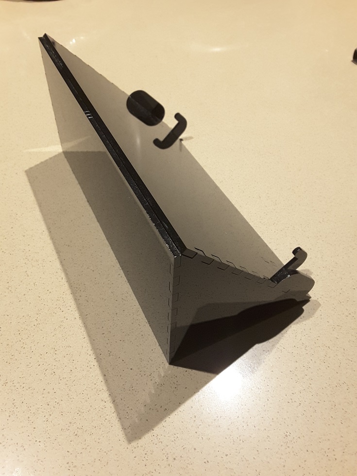
The acrylic laser cut tablet stand
The acrylic laser cut stand was made at the local makerspace in Adelaide. They have lots of cool equipment like 3D printers, laser cutting, CNC routers, woodworking, metal working. You simply sign up for membership and go in and use the equipment. Volunteers are onsite to help you with your project and how to use the equipment.
Battery Management
Tablet and laptop makers want to achieve the the longest battery run time. That’s a selling point and what people want, however this can reduce the battery life to only a few years in always on applications. Lithium batteries do not like to remain fully charged for long periods of time. To increase the battery life and reduce the chances of the lithium battery swelling, there are apps that allow you to control the battery charging profile with the goal to only charge to 80%, etc. On Android this requires that your tablet or phone has been rooted. Check out Battery Charge Limit. In my case this does not work on my Google Nexus 7 (2012) pictured above.
This is the perfect project for the energy conscious gadget geek homeowner or business. As we know energy efficient homes normally have solar panels installed. In Australia normal retail Feed In Tariffs (FIT) for solar are lower than your normal usage tariff so it is wise to try and use power generated from your own solar system first and limit power use from the grid.
If you want to change your habits and reduce your power bill and become more sustainable, you really need to know your generation in real time. That’s where this real-time energy display comes into play.
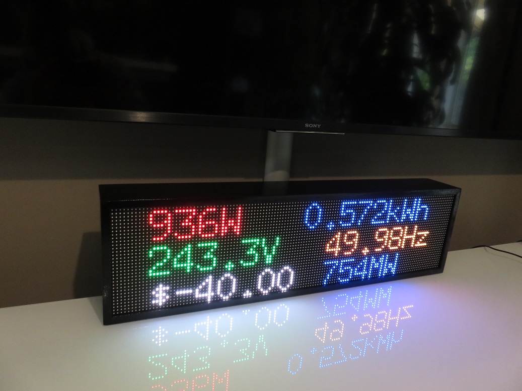
Built from 32×64 RGB matrix LED panels connected to a Raspberry Pi, it connects to your home network and grabs data directly from your inverter and AEMO’s website. AEMO is the Australian Energy Market Operator and controls the wholesale electricity costs in the NEM (Nation Electricity Market).
The top line shows the instantaneous power being generated followed by the daily generated energy (Right) for that day. These figures are very useful and come directly from your inverter.
The middle line is displaying the mains voltage and frequency at the inverter. The voltage is important as there is too much solar generation in some areas and this pushes up the voltage. If the voltage gets too high the inverter is programmed to reduce the power it is generating or in some cases, total stop generating until the voltage is reduced. It’s becoming a very common issue that I have during low demand months in Spring.
The bottom line is showing the spot wholesale electricity price and the total demand for the state. In this case both values are for South Australia. This data is pulled from AEMO in near real-time. Why is this important? Well some companies like Amber Electric now offer wholesale energy prices that change in each 30min internal. For switched on energy users, they can save lots of money but using electricity when prices are cheap or even negative (Yes, retailers can be paid for you to use electricity) and reduce their usage when prices are high.
First working prototype
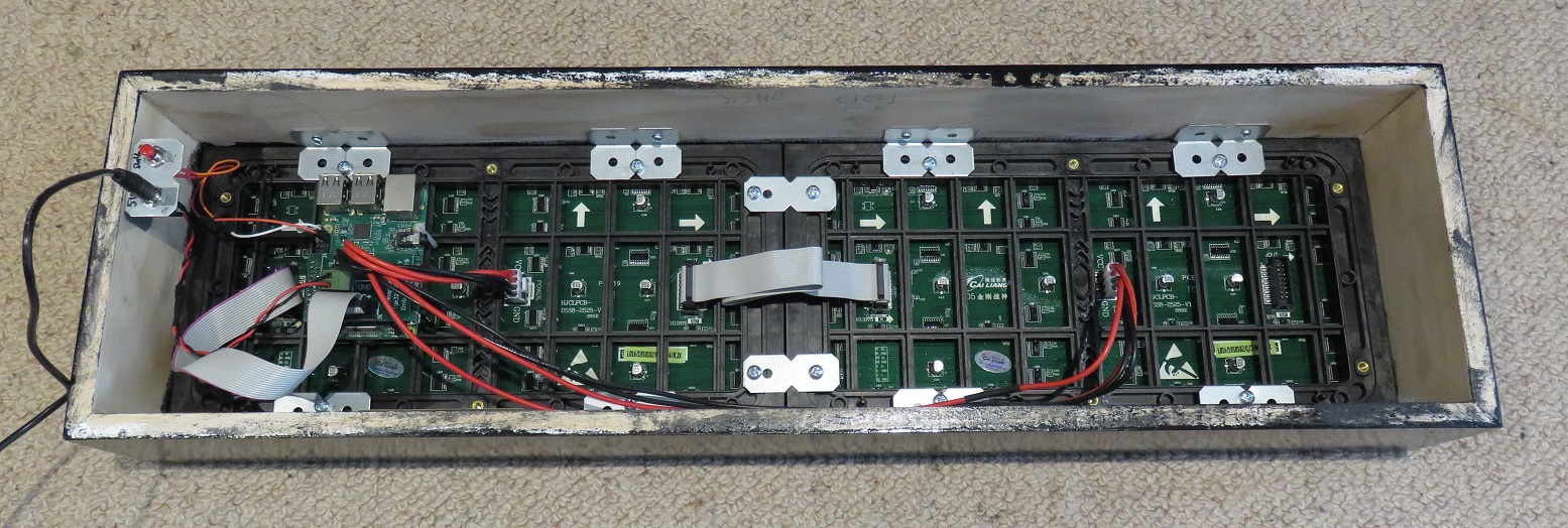
The software is a simple custom python script that gets the data of interest and then uses a library called LED_Matrix written by Henner Zeller to display it. I can also display my import and export to grid data if required, however I show this on a Android Dashboard.
The hardware uses a Raspberry Pi 3B with a custom designed interface board for the display control. A red button can be used to shutdown the Raspberry Pi’s OS before removing power however this is not really needed.
This display can be reprogrammed to display anything from graphics to stock prices etc. If there is an API to get the data, it can normally be displayed. The possibilities are endless.
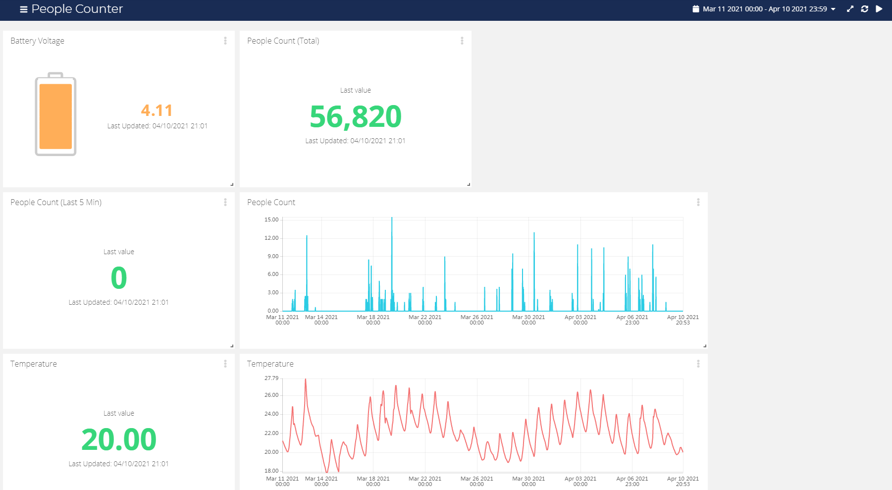
This ultralow powered people counter can be used to count people or animals passing by the sensor. It uses a sensor that detects heat (Infrared light) of the moving object. The sensor has about a 4-5M detection beam and needs no reflector or hardware on the other side. It can be used in both indoor and outside environments.
Data is collected and transmitted in near real-time via a LoRaWAN network to an application server. For each set interval period (Recommend 10, 15, 30 Minutes), the sensor reports the total number of people that has passed allowing operators to gain usage data based on time and or day. The days of having to return to site to collect data have also gone.
Specifications
LoRa Band
Default AU915 or US915 (Firmware Change)
Transmission Power
Up to 20dBm (100mW)
Compatible Networks
TTN or custom
Temperature range
-20C to +50C
Ingress Protection
IP64 (Do not jet water into sensor)
Sensor Distance
4 to 5 metres max.
Beam Angle
< 40 deg
Directional detection
No
Transmission rate
10 min+
Battery Type
ER14505 3.6V 2600mAh Lithium Thionyl Chloride
Estimated Battery Life *Note1
10min TX Intervals (250 events per day)
Appox. 5 Years
30min TX Intervals (250 events per day)
Appox. 8 Years
Internal Temperature Sensor
DS18B20 (Optional)
Note 1. Based on 25 Deg C, SF8BW125 and 20dBm TX power
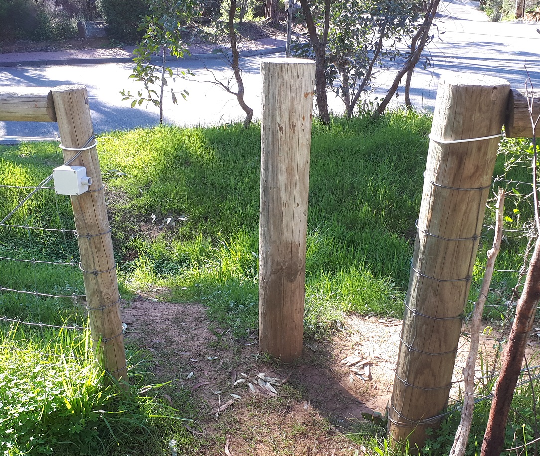
Device Placement
If placed outside the sensor must face away from the sun. Do not point sensor up. Sensor must be horizonal or pointed down at a very small angle.
The detector should be mounted to a post or wall at waist height. 4 mounting holes are provided when the top lid of the enclosure is open. Attaching to metal posts or metal buildings will affect transmission range.
Do not open device in wet or high humidity environments. If the enclosure has to be open in high humidity environment >50%, place a small desiccant bag inside before sealing up.
Monitoring Parks and Reserve use.Restricted Access path monitoringBasic data portal
Data Format
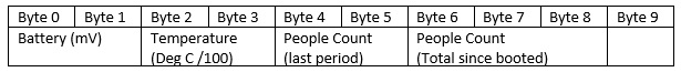
All values are stored as unsigned integers in big-endian format
Battery level in mV (2 Bytes) 4100 = 4.100V
Temperature (If Installed) in Deg C divide by 100 (2 Bytes Signed!), so 2100 would be 21.00Deg
People Count Last interval only (2 Bytes)
People Count Total since battery installed or device reset – Overflows @ 16,777,216 counts (3 Bytes)
TTN Decoder Function
If using The Things Network, a decoder option can be added to decode the values to human readable values at the TTN server.
function Decoder(bytes, port) {
// Decode an uplink message from a buffer
if (port == 2)
{
var battery = (bytes[0]<<8 | bytes[1]);
// Temperature can be signed!!
var temperature;
if (bytes[2] & 0x80) // Check sign bit
temperature = (32768-((bytes[2]&0x7F)<<8 | bytes[3]))*-1;
else temperature = (bytes[2]<<8 | bytes[3]);
var people_int = (bytes[4]<<8 | bytes[5]);
var people_tot = (bytes[6]<<16 | bytes[7]<<8 | bytes[8]);
}
return {
battery: battery/1000,
temperature: temperature/100,
people_int: people_int,
people_tot: people_tot
}
}
Command Set
AT+<CMD>? : Help on <CMD>
AT+<CMD> : Run <CMD>
AT+<CMD>=<value> : Set the value
AT+<CMD>=? : Get the value
ATZ: Trig a reset of the MCU
AT+FDR: Reset Parameters to Factory Default, Keys Reserve
AT+DEUI: Get or Set the Device EUI
AT+DADDR: Get or Set the Device Address
AT+APPKEY: Get or Set the Application Key
AT+NWKSKEY: Get or Set the Network Session Key
AT+APPSKEY: Get or Set the Application Session Key
AT+APPEUI: Get or Set the Application EUI
AT+ADR: Get or Set the Adaptive Data Rate setting. (0: off, 1: on)
AT+TXP: Get or Set the Transmit Power (0-5, MAX:0, MIN:5, according to LoRaWAN Spec)
AT+DR: Get or Set the Data Rate. (0-7 corresponding to DR_X)
AT+DCS: Get or Set the ETSI Duty Cycle setting – 0=disable, 1=enable – Only for testing
AT+PNM: Get or Set the public network mode. (0: off, 1: on)
AT+RX2FQ: Get or Set the Rx2 window frequency
AT+RX2DR: Get or Set the Rx2 window data rate (0-7 corresponding to DR_X)
AT+RX1DL: Get or Set the delay between the end of the Tx and the Rx Window 1 in ms
AT+RX2DL: Get or Set the delay between the end of the Tx and the Rx Window 2 in ms
AT+JN1DL: Get or Set the Join Accept Delay between the end of the Tx and the Join Rx Window 1 in ms
AT+JN2DL: Get or Set the Join Accept Delay between the end of the Tx and the Join Rx Window 2 in ms
AT+NJM: Get or Set the Network Join Mode. (0: ABP, 1: OTAA)
AT+NWKID: Get or Set the Network ID
AT+FCU: Get or Set the Frame Counter Uplink
AT+FCD: Get or Set the Frame Counter Downlink
AT+CLASS: Get or Set the Device Class
AT+JOIN: Join network
AT+NJS: Get the join status
AT+SENDB: Send hexadecimal data along with the application port
AT+SEND: Send text data along with the application port
AT+RECVB: Print last received data in binary format (with hexadecimal values)
AT+RECV: Print last received data in raw format
AT+VER: Get current image version and Frequency Band
AT+CFM: Get or Set the confirmation mode (0-1)
AT+CFS: Get confirmation status of the last AT+SEND (0-1)
AT+SNR: Get the SNR of the last received packet
AT+RSSI: Get the RSSI of the last received packet
AT+TDC: Get or set the application data transmission interval in ms
AT+DTIME: Get or set the sensor deadtime in ms
AT+PORT: Get or set the application port
AT+CHS: Get or Set Frequency (Unit: Hz) for Single Channel Mode
AT+CHE: Get or Set eight channels mode,Only for US915,AU915,CN470
A lot of us started developing for the Multitech mDOT module, but as developers would be aware this device uses 2 mm pitch headers that will not plug into bread board or even vero board. There was no simple test board with 2.54mm pitch headers therefore if you want to prototype for this device you need to buy their developer board which is quite large and also not cheap at just over $100 Australian.
Introducing the mDOT LoRa Test Board. IO pins are easily accessible on standard 2.54mm pitch headers than can be brought locally through outlets like Jaycar. A on-board very low quiescent current regulator allows many days of operation from a battery supply.
Schematic Attached.
Specifications:
Input voltage: 2.7V to 11.8V – Runs direct from Lithium Ion/Polymer cells.
Pololu S7V8F3
Uses the standard off the shelf FTDI TTL-232R-3V3 cable for firmware upgrades and custom programming.